V-65A-R1VB01
2-port sector antenna, 2x 1695–2690 MHz, 65° HPBW, 1x RET
Features and benefits
- Uses the 4.3-10 connector which is 40 percent smaller than the 7-16 DIN connector
Specifications
General specifications
| Antenna Type | Sector |
| Band | Single band |
| Color | Light Gray (RAL 7035) |
| Grounding Type | RF connector inner conductor and body grounded to reflector and mounting bracket |
| Performance Note | Outdoor usage |
| Radome Material | Fiberglass, UV resistant |
| Radiator Material | Low loss circuit board |
| Reflector Material | Aluminum |
| RF Connector Interface | 4.3-10 Female |
| RF Connector Location | Bottom |
| RF Connector Quantity, mid band | 2 |
| RF Connector Quantity, total | 2 |
Remote electrical tilt (ret) information
| RET Hardware | CommRET v2 |
| RET Interface | 8-pin DIN Female | 8-pin DIN Male |
| RET Interface, quantity | 1 female | 1 male |
| Input Voltage | 10–30 Vdc |
| Internal RET | Mid band (1) |
| Power Consumption, active state, maximum | 10 W |
| Power Consumption, idle state, maximum | 2 W |
| Protocol | 3GPP/AISG 2.0 (Single RET) |
Dimensions
| Width | 160 mm | 6.299 in |
| Depth | 115 mm | 4.528 in |
| Length | 1493 mm | 58.780 in |
| Net Weight, without mounting kit | 8.5 kg | 18.739 lb |
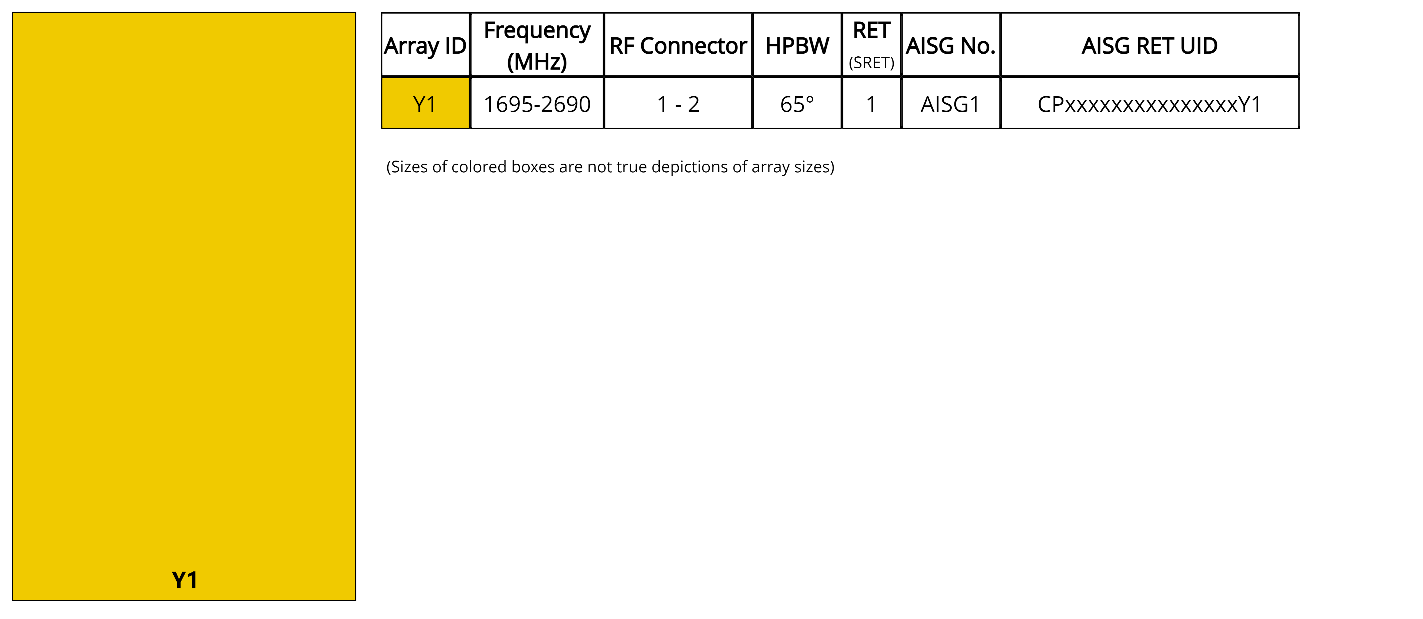
Array layout
| Click on image to enlarge. |
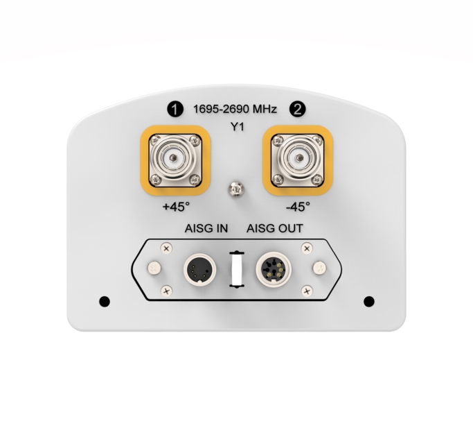
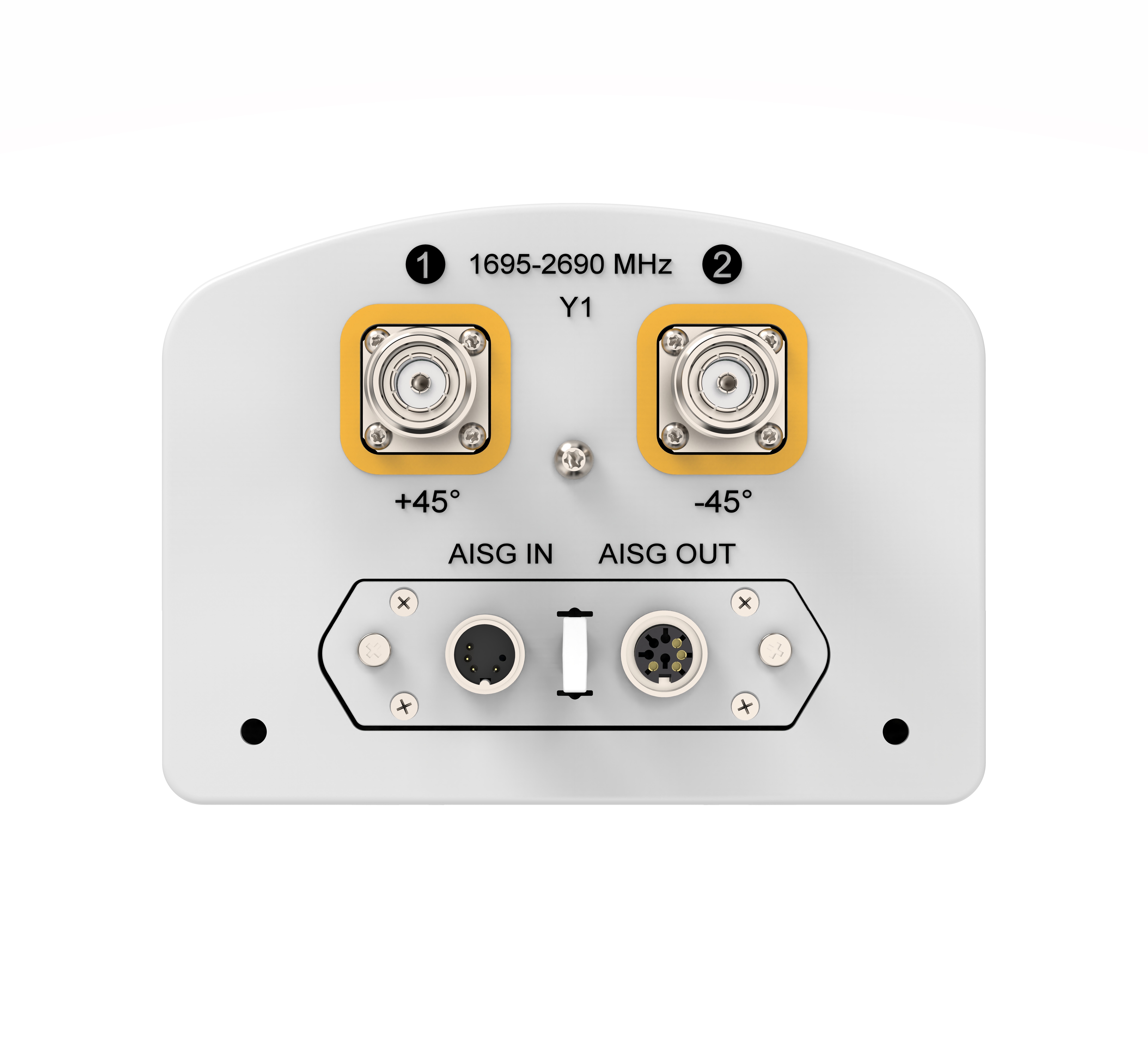
Port configuration
| Click on image to enlarge. |
Electrical specifications
| Impedance | 50 ohm |
| Operating Frequency Band | 1695 – 2690 MHz |
| Polarization | ±45° |
| Total Input Power, maximum | 400 W |
Electrical specifications
| Y1 | Y1 | Y1 | Y1 | |
| Frequency Band, MHz | 1695–1995 | 1920–2300 | 2300–2500 | 2490–2690 |
| RF Port | 1,2 | 1,2 | 1,2 | 1,2 |
| Gain, dBi | 17.6 | 18.0 | 18.5 | 18.5 |
| Beamwidth, Horizontal, degrees | 70 | 67 | 63 | 59 |
| Beamwidth, Vertical, degrees | 6.4 | 5.7 | 5.1 | 4.8 |
| Beam Tilt, degrees | 2–12 | 2–12 | 2–12 | 2–12 |
| USLS (First Lobe), dB | 17 | 18 | 15 | 17 |
| Front-to-Back Ratio, Copolarization 180° ± 30°, dB | 26 | 26 | 27 | 27 |
| CPR at Boresight, dB | 19 | 21 | 18 | 20 |
| Isolation, Cross Polarization, dB | 28 | 28 | 28 | 28 |
| VSWR | Return loss, dB | 1.5 | 14.0 | 1.5 | 14.0 | 1.5 | 14.0 | 1.5 | 14.0 |
| PIM, 3rd Order, 2 x 20 W, dBc | -153 | -153 | -153 | -153 |
| Input Power per Port, maximum, watts | 200 | 200 | 200 | 200 |
Mechanical specifications
| Wind Loading @ Velocity, frontal | 112.0 N @ 150 km/h (25.2 lbf @ 150 km/h) |
| Wind Loading @ Velocity, lateral | 199.0 N @ 150 km/h (44.7 lbf @ 150 km/h) |
| Wind Loading @ Velocity, rear | 208.0 N @ 150 km/h (46.8 lbf @ 150 km/h) |
| Wind Speed, maximum | 241 km/h (150 mph) |
Packaging and weights
| Width, packed | 285 mm | 11.220 in |
| Depth, packed | 240 mm | 9.449 in |
| Length, packed | 1730 mm | 68.110 in |
| Weight, gross | 13.6 kg | 29.983 lb |
Regulatory compliance/certifications
| Agency | Classification |
|
CE
|
Compliant with the relevant CE product directives |
| ISO 9001:2015 | Designed, manufactured and/or distributed under this quality management system |
| UK-ROHS | Compliant |
General specifications
| Antenna Type | Sector |
| Band | Single band |
| Color | Light Gray (RAL 7035) |
| Grounding Type | RF connector inner conductor and body grounded to reflector and mounting bracket |
| Performance Note | Outdoor usage |
| Radome Material | Fiberglass, UV resistant |
| Radiator Material | Low loss circuit board |
| Reflector Material | Aluminum |
| RF Connector Interface | 4.3-10 Female |
| RF Connector Location | Bottom |
| RF Connector Quantity, mid band | 2 |
| RF Connector Quantity, total | 2 |
Remote electrical tilt (ret) information
| RET Hardware | CommRET v2 |
| RET Interface | 8-pin DIN Female | 8-pin DIN Male |
| RET Interface, quantity | 1 female | 1 male |
| Input Voltage | 10–30 Vdc |
| Internal RET | Mid band (1) |
| Power Consumption, active state, maximum | 10 W |
| Power Consumption, idle state, maximum | 2 W |
| Protocol | 3GPP/AISG 2.0 (Single RET) |
Dimensions
| Width | 160 mm | 6.299 in |
| Depth | 115 mm | 4.528 in |
| Length | 1493 mm | 58.780 in |
| Net Weight, without mounting kit | 8.5 kg | 18.739 lb |
Electrical specifications
| Impedance | 50 ohm |
| Operating Frequency Band | 1695 – 2690 MHz |
| Polarization | ±45° |
| Total Input Power, maximum | 400 W |
Electrical specifications
| Y1 | Y1 | Y1 | Y1 | |
| Frequency Band, MHz | 1695–1995 | 1920–2300 | 2300–2500 | 2490–2690 |
| RF Port | 1,2 | 1,2 | 1,2 | 1,2 |
| Gain, dBi | 17.6 | 18.0 | 18.5 | 18.5 |
| Beamwidth, Horizontal, degrees | 70 | 67 | 63 | 59 |
| Beamwidth, Vertical, degrees | 6.4 | 5.7 | 5.1 | 4.8 |
| Beam Tilt, degrees | 2–12 | 2–12 | 2–12 | 2–12 |
| USLS (First Lobe), dB | 17 | 18 | 15 | 17 |
| Front-to-Back Ratio, Copolarization 180° ± 30°, dB | 26 | 26 | 27 | 27 |
| CPR at Boresight, dB | 19 | 21 | 18 | 20 |
| Isolation, Cross Polarization, dB | 28 | 28 | 28 | 28 |
| VSWR | Return loss, dB | 1.5 | 14.0 | 1.5 | 14.0 | 1.5 | 14.0 | 1.5 | 14.0 |
| PIM, 3rd Order, 2 x 20 W, dBc | -153 | -153 | -153 | -153 |
| Input Power per Port, maximum, watts | 200 | 200 | 200 | 200 |
Mechanical specifications
| Wind Loading @ Velocity, frontal | 112.0 N @ 150 km/h (25.2 lbf @ 150 km/h) |
| Wind Loading @ Velocity, lateral | 199.0 N @ 150 km/h (44.7 lbf @ 150 km/h) |
| Wind Loading @ Velocity, rear | 208.0 N @ 150 km/h (46.8 lbf @ 150 km/h) |
| Wind Speed, maximum | 241 km/h (150 mph) |
Packaging and weights
| Width, packed | 285 mm | 11.220 in |
| Depth, packed | 240 mm | 9.449 in |
| Length, packed | 1730 mm | 68.110 in |
| Weight, gross | 13.6 kg | 29.983 lb |
| Click on image to enlarge. |
| Click on image to enlarge. |
Regulatory compliance/certifications
| Agency | Classification |
|
CE
|
Compliant with the relevant CE product directives |
| ISO 9001:2015 | Designed, manufactured and/or distributed under this quality management system |
| UK-ROHS | Compliant |
Documentation & downloads